A
Control System for Solar Water Heater Type HOT07BC.
Operation
Specification
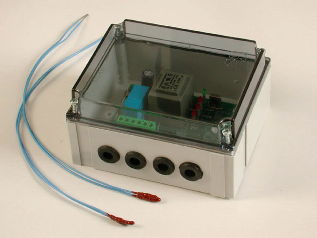
Description:
The
computerized, virtual
thermostat controls one or two
thermometers (sensors). The first one is located on
the outlet of the sun radiation collector, and the
other on the boiler’s outlet. The outlet boiler's
thermometer is option only. The system operation
with or without outlet Sensor.
The
virtual thermostat
checks the temperature (heat) of the collector and
the boiler (If outlet existing). While using a
pump, transfers hot water from the collector to the
boiler.
The
computerized, virtual
thermostat also to measure the functions
of the system and reports its status through warning
red light.
Normal Operation
Range:
1. The temperature
of the collector is under 29°C. The
pump does
not operate. Over 29°C, The system operates
according to the control rules.
2. The temperature of
the collector calculates the temperature of the
boiler. The pump's according operation the
calculation.
3.
If the
fluid (water) temperature in the collector is under
3°C. The PUMP will operate until the
temperature collector warms up to 7°C. (Anti
freezing).
This function is option
with little jumper.
4. In
a standard domestic application, if the outlet fluid
(water) temperature from the collector warms up to
91°C or higher, the PUMP remains in an
special operating mode. and works 10 minutes and
then the temperature warms down.
5. Max.
working temperature range: +125°C ~ -20°C.
Installation kit:
1. The installation kit
contains:
a. A computerized
Virtual thermostat
including 1 sensor.
b. 1 sensor housing
without sensor.
c. Installation
accessories set.
d. Instructions pages.
2. You can install
the boiler at any low place. There is no need
to install it above the collector, as previously
accepted in the old systems. It is recommended to
install the boiler as close as possible to the water
consumer.
3. Open the bolts of
the virtual thermostat,
remove the sensor(s) and install them in the
sensor(s) housing. Using an extension cable, connect
the sensor(s) to the controller at the collector
(and Boiler) points, respectively. Secure the wires
of the sensor(s), at the end of the sensor’(s)
housing by inserting a clamp (a rubber band or a
dowel).
4. The
virtual thermostat
contains a miniature computer. As any other
sensitive system, it should be protected from sun or
rain, by installing it in a shaded and protected
place. The cables to the sensor(s) and to the
system must be resist all weather conditions.
Operation
Instructions:
1. After connecting all
the electrical cables according to the drawing on
the back page, recheck to ascertain that there is no
error or loose connection. The computer identifies
any error.
2. Set the operation
switch OFF. Operate the main Switch to 230 V
and ascertain that the
green POWER light is on and that the
collector lights blink first and then remain
constantly on. This is a self-test process.
3. Set the operation
switch to MAN. Ascertain that the
green POWER
light and the PUMP light are on. At this
stage, the pump operates a minute and stop.
4. Turn the operation
switch to the left, to its AUTO position (two
clicks).
Ascertain that the
green POWER
light is on and that the COLLECTOR and
BOILER lights blink and then turn then off.
If
red light blinks,
there is either a short-circuit or a break in the
cable of those blinking lights.
Note:
For most operation, we
recommended install only one collector sensor.
You can use at 2 sensors,
if you have 8 or more collectors ranch.
Position Selector Switch
1
MAN
position:
a. Green
POWER light indicate on.
b.The pump
operates constantly.
c. The
electronic system is in a reset status (no control).
d. Green
PUMP light indicates that the pump constantly
operates.
e.
Red COLLECTOR
light is off.
2
OFF
position:
a.
Green POWER
light indicate on.
b. The
red COLLECTOR
light is constantly on.
c.
The
pump is physically disconnected from the system
and will not operate under any condition.
3
AUTO
position:
a. a.
Green POWER light indicate on.
b. Normal
operation: The system operates according to the
control rules.
Wait and
ascertain according to the collector temperature at
green PUMP
light.
c. Red
COLLECTOR light off.
Jumper selector
We Have 2
jumpers: 1. Anti freezing jumper, for cancellation
the option.
2. High
temperature mixing the water for more insert
energy to
the boiler. It’s working more then 65c.
More options: Anti calcified deposits.
Display connection for read
the temp’.
PC software for collect hot
histogram.
(need adapter + software
file).
And more.
The computerized
THERMOSTAT can handle all the problems which may
occur in forced solar systems control. Act only in
according to the instructions. |